
The phone case mold development process turns an approved product design into repeatable molded parts. It moves through device and material definition, design-for-manufacturing review, tool design and fabrication, trial molding, controlled corrections and production release. A finished mold or one attractive sample is not enough: the case must fit, function and repeat consistently under the agreed production conditions.
This guide focuses on molded TPU and PC components and related composite case structures. Leather covering, aramid laminates and liquid-silicone systems require their own process review. For a custom phone-case project, start with Kejie’s OEM/ODM development service to discuss whether a current platform can meet your brief before committing to new tooling.
Discuss your phone case design with Kejie
Put mold ownership and access in the project brief
Ask the quotation to identify the tool, contracting parties, permitted users, exclusivity scope, storage location, maintenance charges and transfer procedure. Record which drawings and files are delivered, when access is available and what happens if production stops. These are points to agree in writing, not ownership terms automatically included with a tooling payment.
First decide whether the project needs a new mold
A new logo does not automatically require a new mold. Separate changes to appearance from changes to molded geometry, then confirm which existing tool and exact device version could be used.
Compare OEM and ODM sourcing routes before agreeing on design, tooling and sample approval.
| Requested change | Likely review route | Confirm before committing |
|---|---|---|
| Printed logo or graphic | Existing platform plus decoration review | Usable print area, artwork and adhesion requirements |
| Color or surface finish | Material/finish and sample review | Resin grade, texture and process implications |
| Different opening, retention lip or stand mount | Engineering and tooling review | Device reference, geometry and release method |
| New phone model or proprietary shape | Model-specific fit and new/modified tool review | Controlled drawing, scope and sample criteria |
A molded embossed logo changes geometry even when its purpose is branding. Likewise, a magnetic case may combine separately molded parts and later assembly; do not assume that a TPU + PC product is always made in one two-shot mold. Browse Kejie’s TPU + PC case collection to establish the product construction you want to discuss.
Define the device, construction and approval target
Use an exact device reference, a revision-controlled 3D model and a dimensioned drawing for critical interfaces. A photograph or a nominal phone size cannot define button actuation, connector access, camera clearance or retention. If the device geometry is not available or confirmed, treat the work as preliminary rather than promising production fit.
- Device: exact model/variant and the reference used to establish its geometry.
- Parts: molded shell, bumper, back panel, camera frame and any purchased or assembled functions.
- Material: intended resin grade, hardness where relevant, color and finish; do not specify only “soft plastic.”
- Critical features: dimensions, datum/reference surfaces and tolerances tied to fit or assembly.
- Appearance: acceptable seam, gate and ejection marks, texture and approved visual limits.
- Project: volumes by model, tooling responsibility, sample requirements and target milestones.
Freeze the input revision used for the quote. If a drawing changes afterward, identify the affected feature and ask whether it changes tool fabrication, sample approval or the production route. Keep separate model variants from being merged into one tool assumption.
Review moldability before cutting the tool
Design for manufacturing, or DFM, checks whether the intended geometry can fill, cool and release without compromising its job on the phone. The design essentials for molded parts cover the underlying geometry considerations. For a phone case, turn those principles into questions about the actual interfaces.
| Design area | Phone-case concern | Question for the review |
|---|---|---|
| Wall transitions | Thick camera surrounds beside thin panels can affect appearance or shape | Are transitions, ribs and local thickness compatible with the resin and finish? |
| Draft and texture | Deep sidewalls or texture can resist release | Is the proposed release direction and draft suitable for this material and surface? |
| Undercuts and retention | Inward lips, hooks or side features can obstruct straight release | Can the part strip safely, or does the tool need a different release mechanism? |
| Radii and corners | Sharp transitions can complicate filling and concentrate stress | Can the geometry be softened while keeping fit and edge clearance? |
| Shrinkage and fit | A tool dimension is not automatically the final case dimension | Which material/process assumptions will be verified on trial parts? |
Flexible TPU may permit release strategies that a rigid PC part cannot tolerate. That is a case-specific engineering decision, not permission to strip every undercut. Avoid copying a universal shrinkage factor, wall thickness or draft angle into the specification; agree them with the toolmaker for the actual resin, shape and surface. A moldability review toolkit helps identify the release and geometry questions to resolve.
Translate the case into a workable mold layout
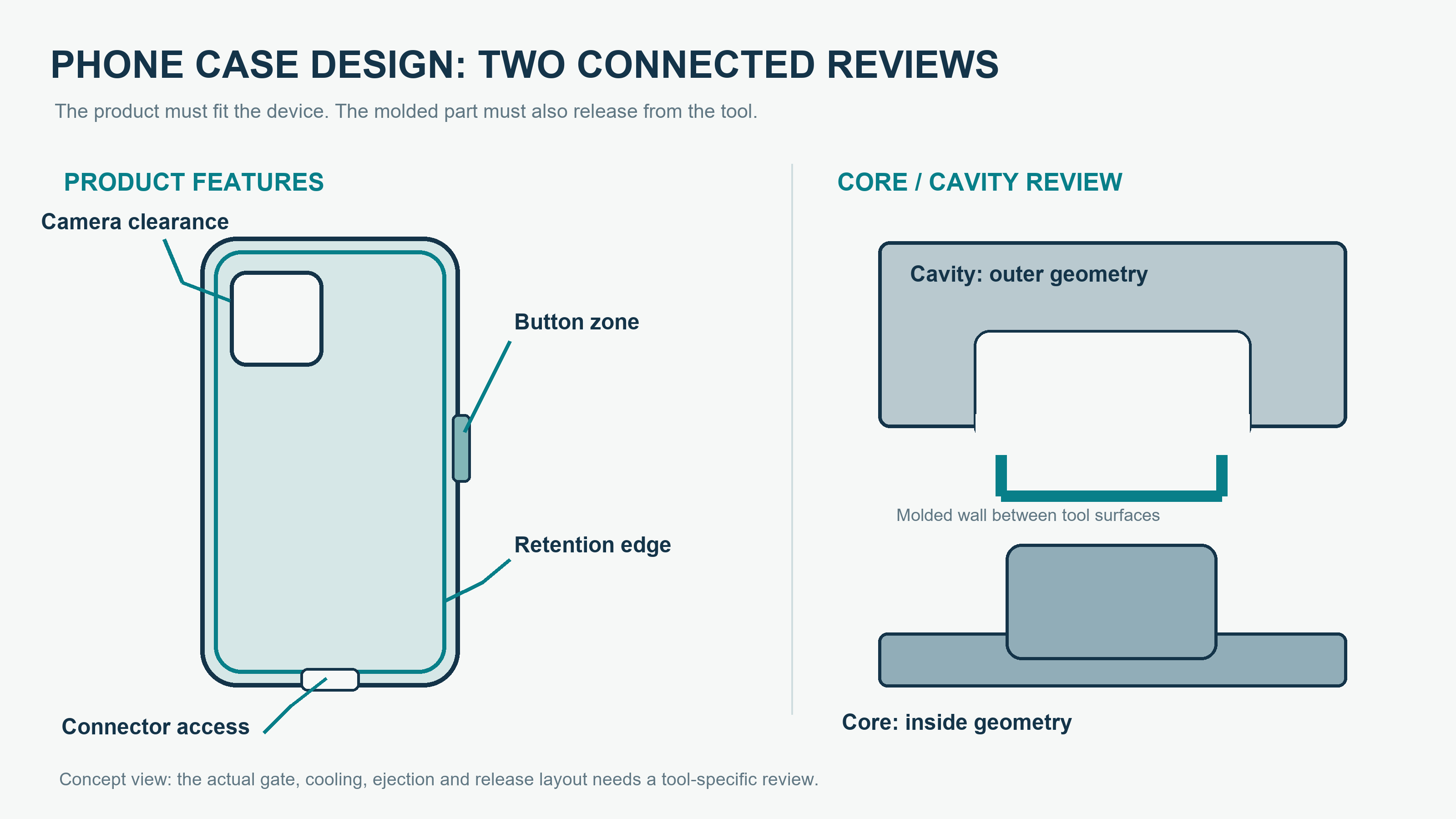
- Camera, button, retention and connector features define device fit.
- The cavity and core define the outside and inside molded surfaces.
- Release direction, parting line, gate and ejection locations need a tool-specific plan.
The tool review should identify what forms each surface and how the part leaves the mold. Review parting-line placement for both appearance and function: a seam or mismatch near a grip edge, retention feature or mating interface can matter more than a mark on an unobtrusive surface.
Gate, venting and ejection
The gate brings resin into the part. Its position influences filling and the remaining mark, while weld-line locations can affect appearance and must be assessed where function matters. Review gate considerations with the visible-face requirements. Venting must let trapped air escape; ejection must remove the part without unacceptable deformation or marks. Ask where those features occur on the case rather than accepting “no marks” as a tooling specification.
Cooling, cavities and tooling scope
Cooling and cycle control influence shape consistency. If several cavities are proposed, ask how cavity identity, filling and inspection will be managed. A larger cavity count is not a quality guarantee. Agree the tool material, expected production use, maintenance, replaceable details and machine compatibility in the project scope rather than choosing a steel grade or tool-life number from a generic article.
Compare what each mold quotation includes
A tooling price is difficult to compare when one offer includes trial corrections and another covers only fabrication. Ask each supplier to identify the included work and the approval evidence for each stage.
- Engineering scope: input drawing revision, DFM review, tool layout and the changes included before design release.
- Trial scope: sample quantities by cavity, trial records, inspection results and the included correction/retrial process.
- Acceptance scope: fit, appearance and function checks, reference samples and production-release evidence.
- Ongoing scope: storage, maintenance, modification handling and any agreed transfer documentation.
- Exclusions: identify additional model variants, new artwork, separate assembly components and changes outside the approved revision.
Record the tool identifier and approved drawing revision alongside the quotation. Clarify which drawings, records or other files will be supplied and when. A lower initial price does not establish a lower total development cost if the required trials or corrections are excluded.
Separate tooling charges from the finished-case quotation
Ask for the scope of each charge rather than comparing only a headline mold price. Development fees and per-unit production costs answer different questions; the quotation should identify what is included and which changes would require a new review.
- Engineering: identify design, DFM and drawing deliverables, including the revision covered by the offer.
- Tool fabrication: confirm the parts, model variants and tool configuration included.
- Trials and corrections: clarify sample quantities, inspection records and the included correction or retrial scope.
- Additional operations: separate purchased components, assembly, decoration and packaging where applicable.
- Later changes: request a scope, cost and milestone review before authorizing a geometry, resin or finish change.
Compare TPU, PC and hybrid case construction when defining the material brief. For logo and packaging projects, review the private-label sourcing guide; branding on an existing platform is not automatically a new-tool project.
Build the tool, then use the first trial to learn
After the design and tool layout are released, fabrication can include machining, electrical discharge machining where needed, fitting, polishing or texture work and assembly of the tool’s operating features. The precise route depends on the tool. Inspection should check the approved layout and important dimensions before trial molding.
- Tool readiness: confirm tool revision, material configuration and trial plan.
- First molding trial: produce identified parts and record the material, cavity and relevant processing conditions.
- Review: inspect fit, dimensions, appearance and intended functions against the brief.
- Correction: classify the issue and authorize a controlled design, tool or process change.
- Repeat trial: verify the correction on a new identified sample set before release.
Suppliers may call these trials T0, T1 or T2, but the names are not a universal acceptance standard. Ask what each trial includes and what constitutes a pass. The injection molding process guide distinguishes mold creation from part production; keep trial evaluation separate from routine bulk manufacture.
Turn trial findings into a useful correction record
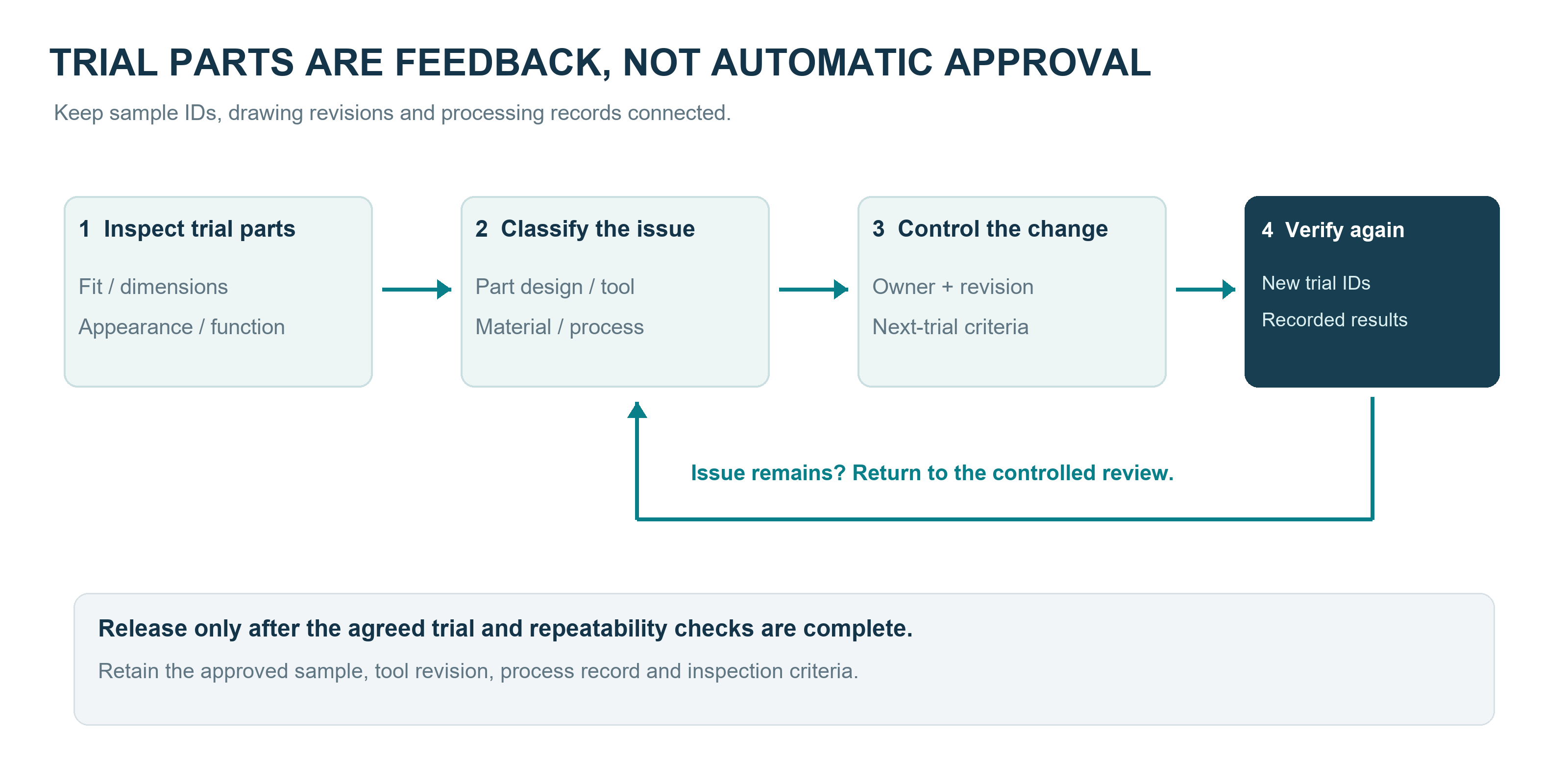
- Inspect identified trial parts.
- Classify the issue: design, tool, material or process.
- Assign a controlled change, owner and next-trial criteria.
- Verify a new sample set; repeat the review if the issue remains.
A visible defect is a finding, not a confirmed root cause. Warpage, incomplete filling, flash or a poor surface can have more than one cause. Fit errors can also originate in the device reference or product design. Compare measurements, cavity identity and processing records before deciding to alter the tool.
| Finding | Investigate first | Record for the next trial |
|---|---|---|
| Poor fit or misaligned openings | Device reference, drawing revision and actual part measurements | Affected model/feature and agreed target |
| Warped panel or uneven edge | Geometry, cooling and material/process conditions | Conditioned sample, location and repeat measurements |
| Flash or difficult release | Shutoff/parting surfaces, release geometry and process | Location, functional effect and correction scope |
| Visible gate, weld or ejection mark | Tool layout, surface limits and processing | Annotated photos and approved appearance criteria |
| Weak assembly or function | Component dimensions, retention and actual accessory combination | Assembly configuration and retest method |
Use one issue list: sample ID, cavity, drawing/tool revision, finding, photo or measurement, suspected cause, action owner, approved change and verification result. Separate “acceptable as agreed” from “must correct.” A polished sample selected from one run does not establish consistency across cavities or production starts.
What should be approved before production?
Approve the finished case and the repeatable route that produces it. A resin certificate does not prove device fit, magnetic compatibility or drop performance. A prototype that fits does not prove a production tool will produce the same result.
| Release item | What to retain | Why it matters |
|---|---|---|
| Geometry and material | Approved drawing, resin specification and tool revision | Prevents uncontrolled substitutions |
| Part and assembly standard | Dated master samples, fit checks and function scope | Defines the actual product being approved |
| Production evidence | Agreed run records, cavity checks and inspection results | Shows repeatability within the approved conditions |
| Appearance and packing | Visual limits, artwork, labels and packing instructions | Keeps finishing and shipment aligned with the case |
| Change and ownership terms | Approval responsibilities, storage, maintenance and transfer terms | Controls future revisions and tooling accountability |
For complex folding or moving structures, additional motion and retention checks may be necessary. The published foldable case manufacturer selection guide expands on that qualification context. Use it for those structures, not as a reason to add hinge tests to every conventional case.
Compare current Kejie platforms before developing new tooling
An existing platform may meet the brief with branding or finish changes. Use these products to make the discussion concrete; neither listing establishes that its mold can be modified, exclusively owned or used for a different phone model.

Matte TPU platform
Discuss the exact model, retention feel, color and branding needs. Distinguish a stock finish change from a geometry change.
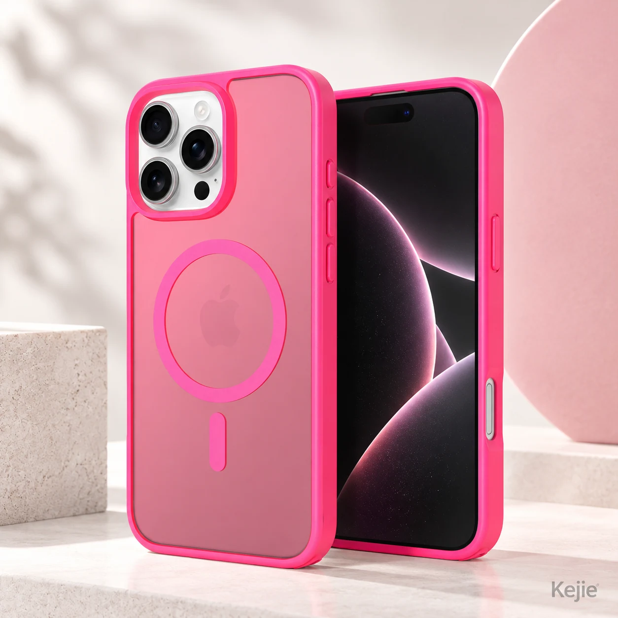
Magnetic TPU + PC platform
Discuss the bumper, rear panel, magnet and assembly as separate requirements. Confirm whether the project reuses a platform or needs a new structure.
Ask Kejie to review your development route
Kejie’s OEM/ODM service covers product direction, engineering coordination, sample review and controlled revisions. Share your intended case and the decisions still open so our team can discuss a suitable starting point and project-specific tooling scope.
- Exact device models and available device/reference data.
- CAD/drawing revision or reference product, plus the requested changes.
- Material, finish, functional parts and assembly requirements.
- Expected volumes by model and target project milestones.
- Fit, appearance, trial and production-acceptance requirements.
Before committing to tooling, confirm the feasibility review, deliverables, trial/revision scope, price, timing and ownership terms in writing.
Phone case mold-development questions
Can a 3D-printed prototype replace molded trial parts?
It can help review geometry or assembly, but its material behavior, surface and production process can differ. Use molded production-intent parts to confirm the tooling route and the agreed product requirements.
Can the same mold cover several phone models?
Only where the actual geometry and tool design support it. Interchangeable details may be feasible for some projects, but similar phone names or overall dimensions do not establish compatibility.
Who owns the mold after development?
Ownership, exclusivity, storage, maintenance, modification rights and transfer arrangements depend on the written agreement. Payment alone should not be treated as a complete statement of those rights.
How long does mold development take?
Request separate milestones for design approval, fabrication, first trial, corrections and production release. Complexity, materials, tool construction and trial findings change the route; a single unqualified number is not a reliable project plan.
 English
 Español de Argentina
 Русский
 Italiano
 日本語
 한국어
 العربية
 Français
 Deutsch